All articles from the Bad Screamer series
As usual, modelling germanium transistor circuits can only go this far, what you actually get in reality can be different from the simulation.
Also, this is about putting components into their unusual modes of functioning: getting a pleasant to the ear distortion can’t be predicted from the sims at all. This is how it is during the tweaking 🙂
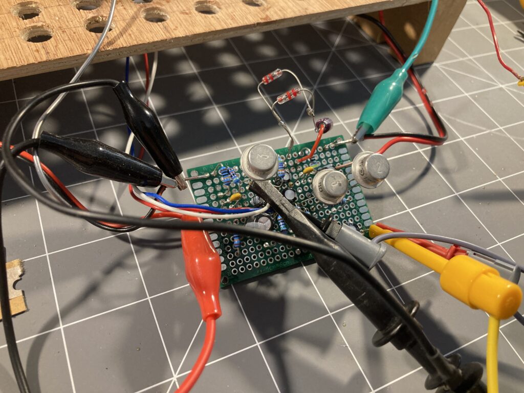
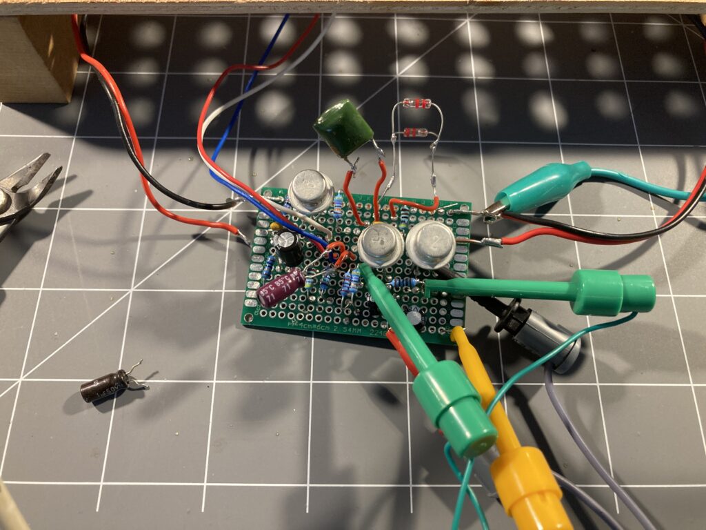
And this is how it looked after:
This is the schematic with changed values:
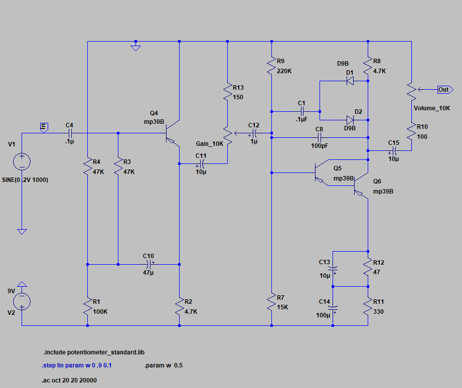
A recap of all the modifications:
- This is a negative ground circuit! The ground connection is “on the top” of the schematics. Don’t want the struggle with a positive ground pedal or voltage inverters people often use to change the supply polarity. It all works just fine like this, only needs relocating couple of components and carefully considering the polarity of the polarized caps.
- these are Germanium diodes (worked much better than silicon diodes or red LEDs), so no more silicon left in this anymore, all Germanium!
- I had to reduce the low frequencies before the last clipping amplifier (lowered C12) and inside the clipping stage itself (lowered C1), otherwise it was too fuzzy. I, however, might let myself choose the value of the C1 with a “character” or “more” switch.
- Lowered C8 from 470 to 100 pF, it was cutting the highs too much. Still thinking about adding some kind of tone control, not sure what it’ll be yet.
- Some resistor tweaks to put transistors into proper bias.
- The mid-boost stack (C13, C14) is working very well, didn’t touch it at all